Table of Contents
Project Overview
In this project, a 1/10th scale RC car uses computer vision techniques to perform lane keeping (staying in the middle of two lane lines) using the camera feed as input. In order to perform feedback control to keep the vehicle in the center of the lane lines, the geometry of the 3D world needs to be processed and understood by the computer vision algorithm.
The algorithm outputs the vehicle’s distance from the center line by understanding the projective transformation happening within the camera. This distance is used to control the vehicle’s steering and keep it in the middle of the lane lines.
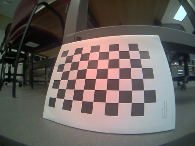
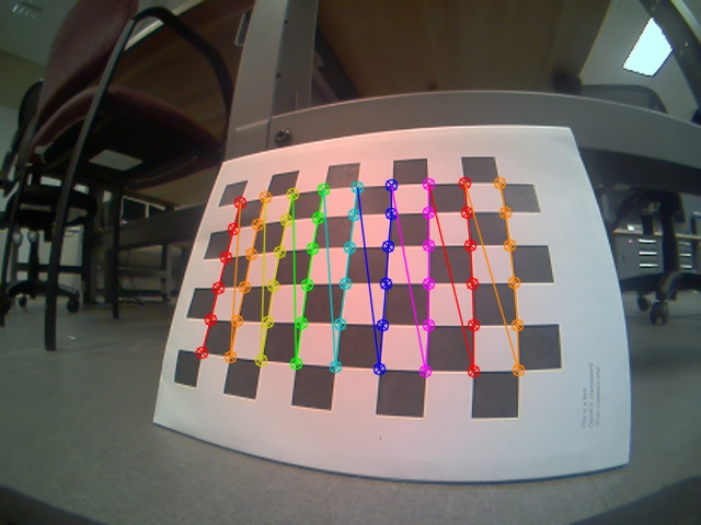
Camera Calibration
In order to remove the effects of lens distortion, camera calibration is done in OpenCV. The camera calibration step gives me the camera calibration matrix and distortion coefficients.
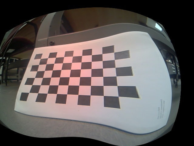
Distortion Correction to Raw Images
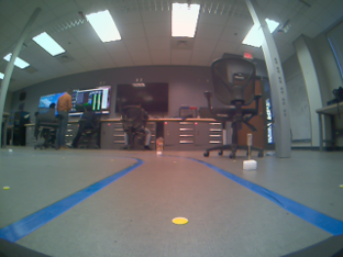
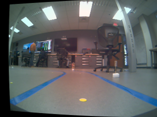
In order to remove the effects of lens distortion, the raw camera feed is undistorted using the camera calibration matrix and distortion coefficients. Below, the left image is the raw camera feed and the right image is the undistorted image.
Blue-color Mask
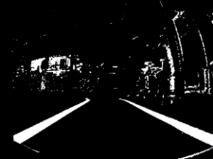
In order to identify the lane lines, I look for blue colors in the HSV color space. The image below shows the detected blue colors in the undistorted image.
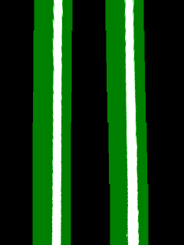
Rectify Images to "Birds-Eye-View"
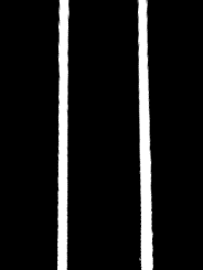
To be able to detect the road lines, the undistorted image is warped to a “birds-eye-view”. In this view, parallel lines remain parallel. This gives us a better idea of the geometry of the 3D world. The following image, shows an undistorted image from a top view.
Lane Line Pixel Polynomial Interpolation
Once we have a birds eye view with a combined threshold we are in a position to identify lines and fit a polynomial to detect the right and left lane lines. The image below shows the interpolated left lane line in blue and the right lane line in right. Since we are using higher order curves to interpolate the lane pixels, this method is robust enough to detect curved lines as well as straight lines.
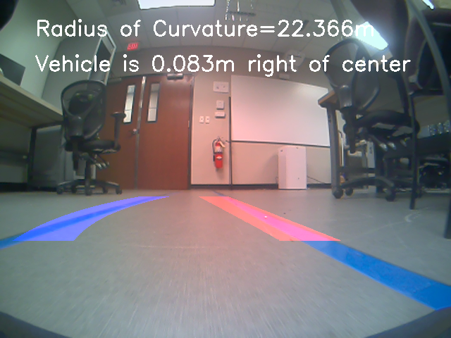
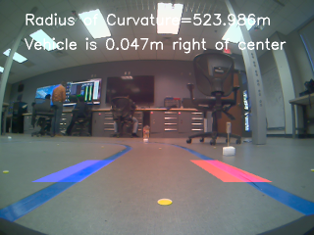
Overlay Lines on Image and Determine Vehicle Distance from Center of Lane
Finally the detected lane lines are overlaid on top of the original image. The distance of the vehicle from the center of the lane is regressed using the perspective projection equations and knowledge of the parameters obtained during calibration. This distance is displayed on the top-left of the screen along with the estimated radius of curvature.
Lane Keeping Demo
Using the detected distance from the center of the lane, an error signal is calculated and proportional control is used to bring the vehicle back to the center. The performance of the vehicle can be seen below. On the left is a third person view of the vehicle and on the right is a first person view showing what the vehicle is seeing.
Traffic Sign Recognition
In order to simulate realistic driving scenarios, the autonomous vehicle must be able to recognize traffic signs. In this step, a dataset of signs was collected and labelled and then trained using a convolutional neural network. The 3 classes predicted by the model are:
- Stop Signs
- Low Speed Limit (25 mph)
- High Speed Limit (45 mph)
Code
					# robust lane keeping
from Quanser.q_essential import Camera2D
from Quanser.product_QCar import QCar
import numpy as np
import math
import logging
import cv2
import pickle
import time
import matplotlib.pyplot as plt
import matplotlib.image as mpimg
import matplotlib.gridspec as gridspec
from tracker import tracker

# -- -- -- -- -- -- -- -- -- -- -- -- -- -- -- -- -- -- -- -- -- -- -- -- -- -- -- -- -- -- -- -- -- -- -- --
## Timing Parameters
sampleRate = 30.0
sampleTime = 1/sampleRate
# -- -- -- -- -- -- -- -- -- -- -- -- -- -- -- -- -- -- -- -- -- -- -- -- -- -- -- -- -- -- -- -- -- -- -- --
# Additional parameters
imageWidth = 640
imageHeight = 480
# -- -- -- -- -- -- -- -- -- -- -- -- -- -- -- -- -- -- -- -- -- -- -- -- -- -- -- -- -- -- -- -- -- -- -- --
## Initialize the CSI cameras
myCam1 = Camera2D(camera_id="3", frame_width=imageWidth, frame_height=imageHeight, frame_rate=sampleRate)
# Initialize the QCar
myCar = QCar()
# -- -- -- -- -- -- -- -- -- -- -- -- -- -- -- -- -- -- -- -- -- -- -- -- -- -- -- -- -- -- -- -- -- -- -- --

## load camera calibration pickle file
calib_result_pickle = pickle.load(open("calibration_pickle.p", "rb" ))
mtx = calib_result_pickle["mtx"]
optimal_camera_matrix = calib_result_pickle["optimal_camera_matrix"]
dist = calib_result_pickle["dist"]

## counter variable
count = 0
gidx = 0
error_last = 0
ts = 0.1;

## Functions
def blue_mask(frame):
    # switch to HSV color format to lift blues from image
    hsv = cv2.cvtColor(frame, cv2.COLOR_BGR2HSV)
    # blue color mask
    lower_blue = np.array([60, 40, 40])
    upper_blue = np.array([150, 255, 255])
    mask = cv2.inRange(hsv, lower_blue, upper_blue)
    return mask

def window_mask(width, height, img_ref, center, level):
    output = np.zeros_like(img_ref)
    output[int(img_ref.shape[0]-(level+1)*height):int(img_ref.shape[0]-level*height), max(0,int(center-width)):min(int(center+width),img_ref.shape[1])] = 1
    return output

## Main Loop
try:
    while True:
        # increment counter
        count += 1

        if count == 75:
            cv2.imwrite("raw_frame.png", frame)
            cv2.imwrite("undistorted_frame.png", undistorted_frame)
            cv2.imwrite("blue_mask_frame.png", mask_img)
            cv2.imwrite("warped_frame.png", warped)
            cv2.imwrite("lane_lines_frame.png", road_warped)
            cv2.imwrite("result_frame.png", result)
            print("All images saved successfully!")

        # Capture RGB Image from CSI
        myCam1.read()

        # store captured frame in variable
        frame = myCam1.image_data

        # undistorted image
        undistorted_frame = cv2.undistort(frame,mtx,dist,None,mtx)

        # filter blues out of image
        mask_img = blue_mask(undistorted_frame)

        bot_width = 1 # percentage of bottom trapezoidal height
        mid_width = .32 # percentage of mid trapezoidal height
        height_pct = .58 # percentage of trapezoidal height
        bottom_trim= .85 # percentage from top to bottom avoiding the hood of the car

        src = np.float32([[imageWidth*(0.5-mid_width/2), imageHeight*height_pct],[imageWidth*(0.5+mid_width/2),imageHeight*height_pct],[imageWidth*(0.5+bot_width/2), imageHeight*bottom_trim],[imageWidth*(0.5-bot_width/2), imageHeight*bottom_trim]])
        offset = imageHeight*0.25
        dst = np.float32([[offset,0],[imageHeight-offset,0],[imageHeight-offset,imageWidth],[offset,imageWidth]])

        #perform the warp perspective transform
        M = cv2.getPerspectiveTransform(src,dst)
        Minv = cv2.getPerspectiveTransform(dst,src)
        warped = cv2.warpPerspective(mask_img,M,(imageHeight,imageWidth),flags=cv2.INTER_LINEAR)

        # show image
        cv2.imshow('warped', warped)
        """
        #Visualize the results before/after warping for a birds-eye view along with the source & destination co-ordinate locations
        plt.figure(figsize = (30,20))
        grid = gridspec.GridSpec(8,2)
        # set the spacing between axes.
        grid.update(wspace=0.05, hspace=0.05)

        plt.subplot(grid[gidx])
        plt.imshow(frame, cmap="gray")
        for i in range(4):
            plt.plot(src[i][0],src[i][1],'rs')
        plt.title('Undistorted Image')

        plt.subplot(grid[gidx+1])
        plt.imshow(warped, cmap="gray")
        for i in range(4):
            plt.plot(dst[i][0],dst[i][1],'rs')
        plt.title('Birds eye view')

        plt.show()
        """

        window_width = 50
        window_height = 80

        #set up the overall class to do the lane line tracking
        curve_centers = tracker(Mywindow_width=window_width, Mywindow_height=window_height, Mymargin = 25, My_ym = 10/720, My_xm = 4/384, Mysmooth_factor=15)

        window_centroids = curve_centers.find_window_centroids(warped)

        # Points used to draw all the left and right windows
        l_points = np.zeros_like(warped)
        r_points = np.zeros_like(warped)

        # points used to find the right & left lanes
        rightx = []
        leftx = []

        # Go through each level and draw the windows
        for level in range(0,len(window_centroids)):
            # Window_mask is a function to draw window areas
            # Add center value found in frame to the list of lane points per left, right
            leftx.append(window_centroids[level][0])
            rightx.append(window_centroids[level][1])

            l_mask = window_mask(window_width,window_height,warped,window_centroids[level][0],level)
            r_mask = window_mask(window_width,window_height,warped,window_centroids[level][1],level)
            # Add graphic points from window mask here to total pixels found
            l_points[(l_points == 255) | ((l_mask == 1) ) ] = 255
            r_points[(r_points == 255) | ((r_mask == 1) ) ] = 255

        # Draw the results
        template = np.array(r_points+l_points,np.uint8) # add both left and right window pixels together
        zero_channel = np.zeros_like(template) # create a zero color channel
        template = np.array(cv2.merge((zero_channel,template,zero_channel)),np.uint8) # make window pixels green
        warpage = np.array(cv2.merge((warped,warped,warped)),np.uint8) # making the original road pixels 3 color channels
        result = cv2.addWeighted(warpage, 1, template, 0.5, 0.0) # overlay the original road image with window results

        #fit the lane boundaries to the left, right center positions found
        yvals = range(0,warped.shape[0])

        res_yvals = np.arange(warped.shape[0]-(window_height/2),0,-window_height)

        left_fit = np.polyfit(res_yvals, leftx, 2)
        left_fitx = left_fit[0]*yvals*yvals + left_fit[1]*yvals + left_fit[2]
        left_fitx = np.array(left_fitx,np.int32)

        right_fit = np.polyfit(res_yvals, rightx, 2)
        right_fitx = right_fit[0]*yvals*yvals + right_fit[1]*yvals + right_fit[2]
        right_fitx = np.array(right_fitx,np.int32)

        left_lane = np.array(list(zip(np.concatenate((left_fitx-window_width/2, left_fitx[::-1]+window_width/2),axis=0),np.concatenate((yvals,yvals[::-1]),axis=0))),np.int32)
        right_lane = np.array(list(zip(np.concatenate((right_fitx-window_width/2, right_fitx[::-1]+window_width/2),axis=0),np.concatenate((yvals,yvals[::-1]),axis=0))),np.int32)

        road = np.zeros_like(frame)
        road_bkg = np.zeros_like(frame)
        cv2.fillPoly(road,[left_lane],color=[255,0,0])
        cv2.fillPoly(road,[right_lane],color=[0,0,255])
        cv2.fillPoly(road_bkg,[left_lane],color=[255,255,255])
        cv2.fillPoly(road_bkg,[right_lane],color=[255,255,255])

        road_warped = cv2.warpPerspective(road,Minv,(imageWidth,imageHeight),flags=cv2.INTER_LINEAR)
        road_warped_bkg= cv2.warpPerspective(road_bkg,Minv,(imageWidth,imageHeight),flags=cv2.INTER_LINEAR)

        base = cv2.addWeighted(frame,1.0,road_warped, -1.0, 0.0)
        result = cv2.addWeighted(base,1.0,road_warped, 1.0, 0.0)
        """
        #Visualize the results of identified lane lines and overlapping them on to the original undistorted image
        plt.figure(figsize = (30,20))
        grid = gridspec.GridSpec(8,2)
        # set the spacing between axes.
        grid.update(wspace=0.05, hspace=0.05)

        #img_plt = plt.subplot(grid[0])
        plt.subplot(grid[gidx])
        plt.imshow(road, cmap="gray")
        plt.title('Identified lane lines')

        #img_plt = plt.subplot(grid[1])
        plt.subplot(grid[gidx+1])
        plt.imshow(result, cmap="gray")
        plt.title('Lane lines overlapped on original image')

        plt.show()
        """

        ym_per_pix = curve_centers.ym_per_pix # meters per pixel in y dimension
        xm_per_pix = curve_centers.xm_per_pix # meters per pixel in x dimension

        curve_fit_cr = np.polyfit(np.array(res_yvals,np.float32)*ym_per_pix,np.array(leftx,np.float32)*xm_per_pix,2)
        curverad = ((1 + (2*curve_fit_cr[0]*yvals[-1]*ym_per_pix + curve_fit_cr[1])**2)**1.5) /np.absolute(2*curve_fit_cr[0])

        # Calculate the offset of the car on the road
        camera_center = (left_fitx[-1] + right_fitx[-1])/2
        center_diff = (camera_center-warped.shape[1]/2)*xm_per_pix
        side_pos = 'left'
        if center_diff <= 0:
            side_pos = 'right'

        # draw the text showing curvature, offset & speed
        cv2.putText(result, 'Radius of Curvature='+str(round(curverad,3))+'m ',(50,50),cv2.FONT_HERSHEY_SIMPLEX,1,(255,255,255),2)
        cv2.putText(result, 'Vehicle is '+str(abs(round(center_diff,3)))+'m '+side_pos+' of center',(50,100), cv2.FONT_HERSHEY_SIMPLEX,1,(255,255,255),2)

        # show lane lines overlayed over original image with geometric text overlayed
        cv2.imshow('result', result)

        ## steering control of QCar
        lane_lower_lim, lane_upper_lim = -0.5, 0.5
        steering_lower_lim, steering_upper_lim = -math.pi/6, math.pi/6

        # map lane center difference to steering angle
        #steering_angle = np.interp(center_diff, [lane_lower_lim, lane_upper_lim], [steering_lower_lim, steering_upper_lim])
        #print("steering angle (deg): ", steering_angle * (180/math.pi))

        Kp, Kd = 1, 0
        error = center_diff
        y = Kp * error + Kd * ((error - error_last)/ts)
        steering_angle = -np.sign(y) * np.minimum(np.abs(y), math.pi/6)
        # store previous error
        error_last = error


        mtr_cmd = np.array([0.07, steering_angle])
        LEDs = np.array([0, 0, 0, 0, 0, 0, 1, 1])
        if mtr_cmd[1] > 0.3:
            LEDs[0] = 1
            LEDs[2] = 1
        elif mtr_cmd[1] < -0.3:
            LEDs[1] = 1
            LEDs[3] = 1
        if mtr_cmd[0] < 0:
            LEDs[5] = 1
        current, batteryVoltage, encoderCounts = myCar.read_write_std(mtr_cmd, LEDs)

        cv2.waitKey(1)

except KeyboardInterrupt:
    print("User interrupted!")

    # stop QCar
    mtr_cmd = np.array([0, 0])
    current, batteryVoltage, encoderCounts = myCar.read_write_std(mtr_cmd, LEDs)

finally:
    # Terminate all objects
    myCam1.terminate()
    myCar.terminate()
# -- -- -- -- -- -- -- -- -- -- -- -- -- -- -- -- -- -- -- -- -- -- -- -- -- -- -- -- -- -- -- -- -- -- -- --