Table of Contents
Project Overview
In this programming assignment, I use the concepts of projective geometry and
homographies to project an image onto a scene in a natural way that respects
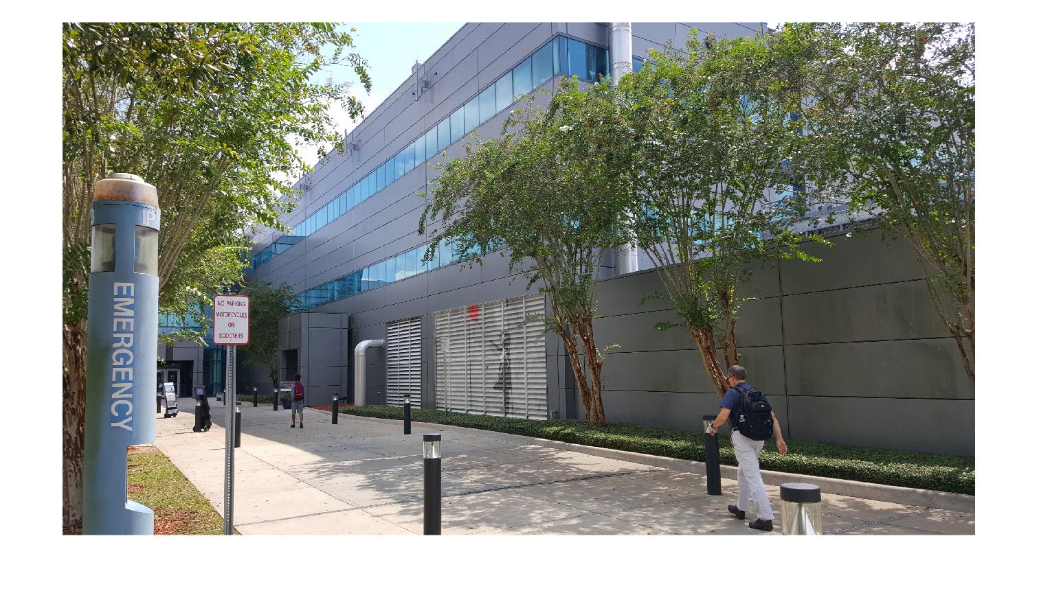
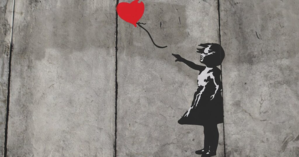
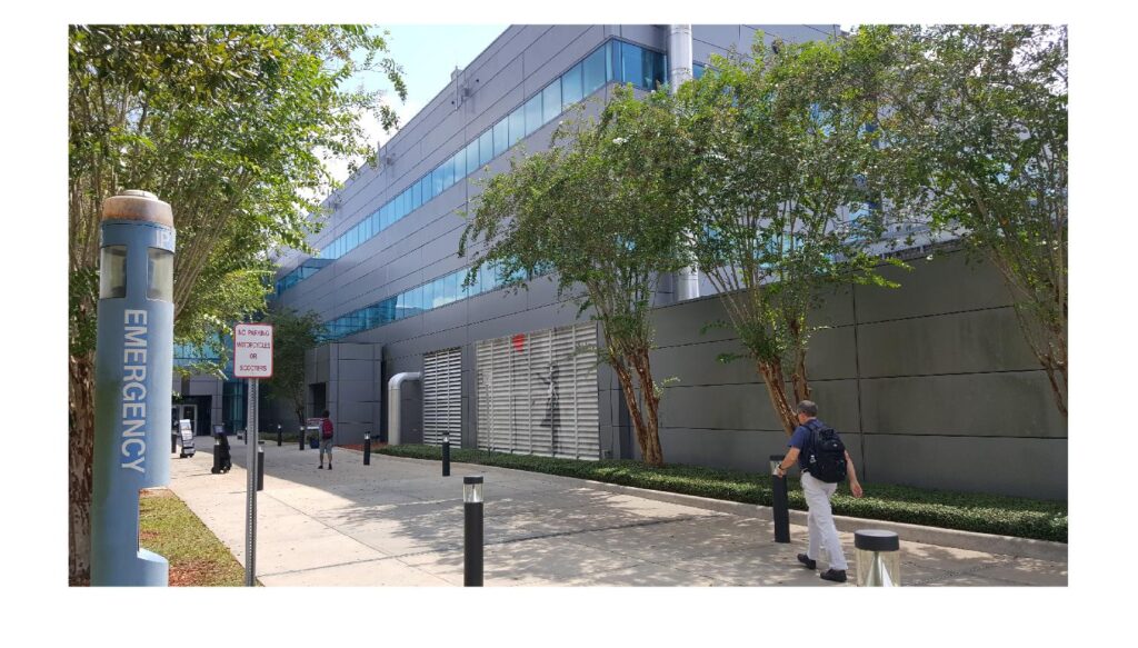
perspective. To demonstrate this, I will project graffiti artwork made by the famous artist Banksy onto the side wall of the FAMU-FSU College of Engineering.
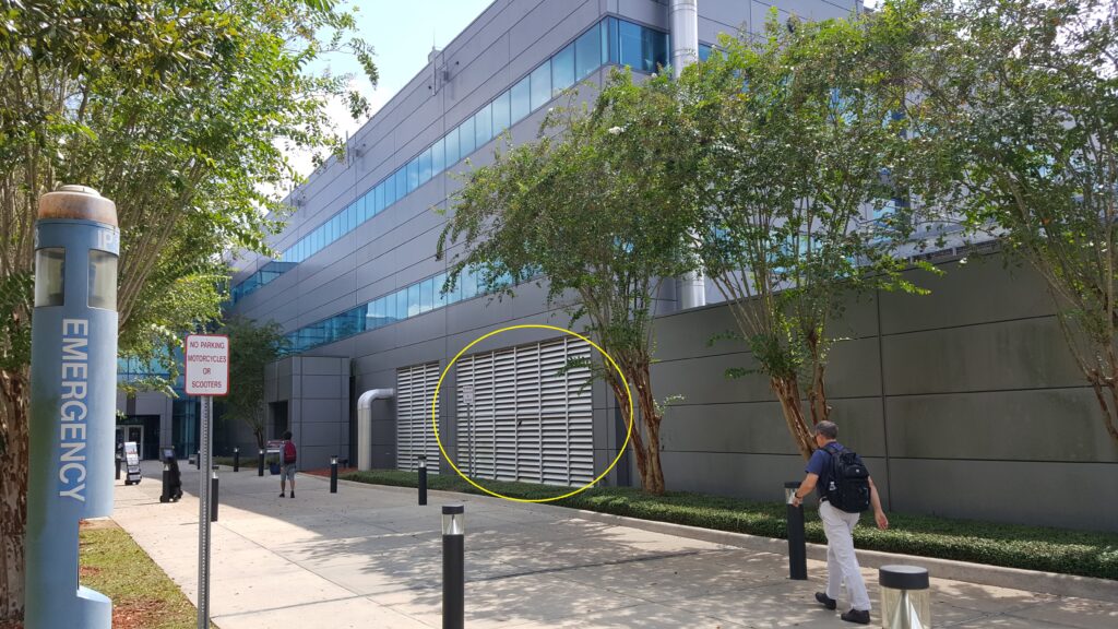
The original image of the College of Engineering is shown below along with the source image of Banksy’s artwork that will be warped onto the wall. The artwork will be placed at the location of the yellow circle.
Homography Estimation
To project one image patch onto another, we need, for each point inside the goal in
the video frame, to find the corresponding point from the logo image to copy over. In
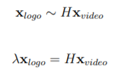
other words, we need to calculate the homography between the two image patches. This homography is a 3×3 matrix that satisfies the following equivalent representations:
Inverse Warping
if we compute the inverse homography, and project all the logo points into the video frame, we will most likely have the case where multiple logo points project to one video frame pixel (due to rounding of the pixels), while other pixels may have no logo points at all. This results in ’holes’ in the video frame where no logo points are mapped. To avoid this, we calculate the projection from video frame points to logo points to guarantee that every video frame gets a point from the logo.
We can then replace every point in the video frame (x_video) with the corresponding point
in the logo (x_logo) using the correspondences (x_image, x_logo).
Result
After computing the homography between the two projective planes and performing the inverse warping, the result is a natural looking representation of the Banksy mural on the College of Engineering’s side wall. We were able to legally showcase our impressive graffiti skills!
Code
					% read logo
logo_img = imread('banksy.jpg');
% Generate logo points (they are just the outer corners of the image)
[logoy, logox, ~] = size(logo_img);
logo_pts = [0 0; logox 0; logox logoy; 0 logoy];

% number of images
num_ima = 1;
test_images = 1;
num_test = length(test_images);

% Initialize the images
video_imgs = cell(num_test, 1);
projected_imgs = cell(num_test, 1);

% points in video to compute homography
video_pts = [2152.5360,1688.3260;2804.2480,1568.6483;2816.4956,2304.9856;2172.9074,2240.3775];
[a,b] = size(video_pts);
video_pts = reshape(video_pts, [a,b,1]);

for i=1:num_test
    video_imgs{i} = imread('CornerCOE.jpg');
    % Find all points in the video frame inside the polygon defined by
    % video_pts
    [ interior_pts ] = calculate_interior_pts(size(video_imgs{i}),...
        video_pts(:,:,test_images(i)));

    % Warp the interior_pts to coordinates in the logo image
    warped_logo_pts = warp_pts(video_pts(:,:,test_images(i)),...
        logo_pts,...
        interior_pts);

    % Copy the RGB values from the logo_img to the video frame
    projected_imgs{i} = inverse_warping(video_imgs{i},...
        logo_img,...
        interior_pts,...
        warped_logo_pts);
end

% display final image with logo
imshow(projected_imgs{1})

%%% functions
function [ interior_pts ] = calculate_interior_pts( image_size, corners )
% calculate_interior_pts takes in the size of an image and a set of corners
% of a shape inside that image, and returns all (x,y) points in that image
% within the corners

[X, Y] = meshgrid(1:image_size(2), 1:image_size(1));
X=X(:);
Y=Y(:);

interior_inds = inpolygon(X,Y,corners(:,1), corners(:,2));
interior_pts = [X(interior_inds),...
    Y(interior_inds)];
end

function [ warped_pts ] = warp_pts( video_pts, logo_pts, sample_pts)
% warp_pts computes the homography that warps the points inside
% video_pts to those inside logo_pts. It then uses this
% homography to warp the points in sample_pts to points in the logo
% image
% Complete est_homography first!
[ H ] = est_homography(video_pts, logo_pts);

len = length(sample_pts);
homogenous_sample_points = [sample_pts, ones(len, 1)];
homogeneous_warped_pts = (H * homogenous_sample_points')';
divider = repmat(homogeneous_warped_pts(:, end), [1, 3]);
homogeneous_warped_pts = homogeneous_warped_pts ./ divider;
warped_pts = homogeneous_warped_pts(:, 1:end-1);

end

function [ H ] = est_homography(video_pts, logo_pts)
% est_homography estimates the homography to transform each of the
% video_pts into the logo_pts
% create lambda functions that generate vectors ax and ay for each point
ax = @(x, xp)[-x(1), - x(2), -1, 0, 0, 0, x(1)*xp(1), x(2)*xp(1), xp(1)];
ay = @(x, xp)[0, 0, 0, -x(1), -x(2), -1, x(1)*xp(2), x(2)*xp(2), xp(2)];

% get number of points (should be 4)
len = length(video_pts);
assert(len == 4);

% initialize matrix A with zeros to prevent resizing in loop
A = zeros(len, 9);

for i=1:len
    A(i * 2 - 1, :) = ax(video_pts(i, :), logo_pts(i, :));
    A(i * 2, :) = ay(video_pts(i, :), logo_pts(i, :));
end

[U, S, V] = svd(A);
H = reshape(V(:, end), [3,3])';

end

function [ projected_img ] = inverse_warping( img_final, img_initial, pts_final, pts_initial )
% inverse_warping takes two images and a set of correspondences between
% them, and warps all the pts_initial in img_initial to the pts_final in
% img_final

pts_final = ceil(pts_final);
pts_initial = ceil(pts_initial);

ind_final= sub2ind([size(img_final,1), size(img_final,2)],...
    pts_final(:,2),...
    pts_final(:,1));
ind_initial = sub2ind([size(img_initial,1) size(img_initial,2)],...
    pts_initial(:,2),...
    pts_initial(:,1));

projected_img = img_final;

for color = 1:3
    sub_img_final = img_final(:,:,color);
    sub_img_initial = img_initial(:,:,color);
    sub_img_final(ind_final) = sub_img_initial(ind_initial)*0.5 + sub_img_final(ind_final)*0.5;
    projected_img(:,:,color) = sub_img_final;
end

end